MY
VERSION OF THE BINOCULAR BOX
(Apologies for
the poor picture quality)
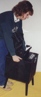
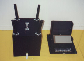
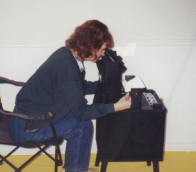
Designed as a
self contained unit, here is the box ready for travel.
Exact dimensions:
14 1/2" H x 16" L x 15" W.
Approx. weight
with binoculars on board: 22 lbs
Binoculars shown
are 10 x 50 Carton Adlerblicks
The mirror is
5" x 10" (for larger binoculars an 8" x 10" mirror is recommended)
.
.
The base is slightly wider than the lid
which is attached by latches, front and back.
Pin clips secure the latches; once
removed the lid can be lifted from the base.
.
 ..... .....
.
The legs, which are stored inside, can
then be attached to the lid to make a stand.
The stand is turned over, the base
goes on top, and the latches re-secured.
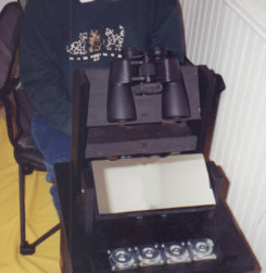
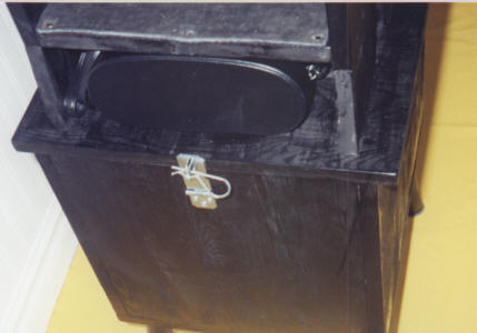
These pictures show the latch assembly,
and where the binocular case is stored.
..
 ..... .....
.
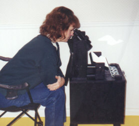
The unit is very
stable and the extra base width is meant to provide a handrest as well
as a grip rail for minor moves. A thin foam rubber liner covers the
binocular platform and brace as well as the shelf below. (A
good place to put your glasses.)
.
The ocular height
allows the viewer to assume a comfortable and stable position.
The binoculars
are angled at 55 degrees below horizontal. The mirror swivels.
The view is
just over 5 degrees wide, and from horizon to a little ways past zenith.
.
 ................ ................
.
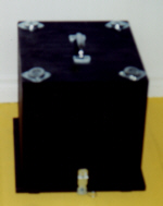
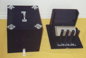
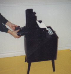
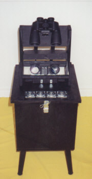
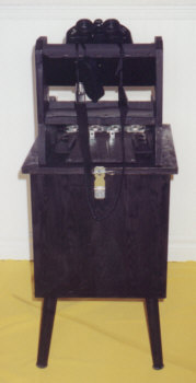
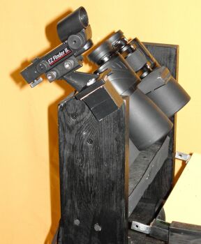
Here is a front
view and a back view. If you look carefully at the back view, you
will notice a nonslip rubber pad for the binocular case to rest on as well
as rubber bumpers on each side for added protection. With the case
in place, the mirror is prevented from swiveling around during transport.
.
 .................... ....................
One of the inherent drawbacks of this
type of mount is with orientation; it can be difficult to know exactly where you
are looking, or to aim at a particular area of the sky with accuracy. After
letting this problem percolate at the back of my mind I came up with the
following solution. I fabricated a simple mounting device to a spare red dot
finder so I could attach it beside the binoculars (see below)...
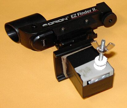
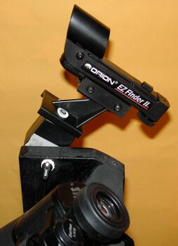 
Using a wingnut and some nylon
washers I can adjust the tension to allow the finder to swivel up and down to
point at a target. This helps to get the box in the correct azimuth (horizontal)
alignment. To aid in getting the correct altitude (which is controlled by the
angle of the mirror) I used a simple marker system by adding strips of white
tape to the base of the mirror and supporting struts (as below)...
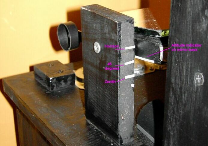
This may be somewhat crude but,
with the 5 degree FOV, it is a simple and effective solution to the orientation
problem.
.
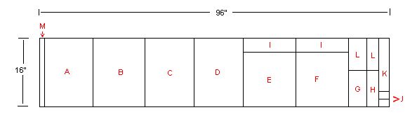
Below are plans
for cutting the pieces from a 3/4" thick pine board - 16" x 96".
.
.
| LETTER |
PIECE |
DIMENSIONS |
| A |
roof of lid |
13 1/2" x 16" |
| B |
base |
15" x 16" |
| C |
long side of
lid |
13" x 16" |
| D |
long side of
lid |
13" x 16" |
| E |
short side of
lid |
13" x 12" |
| F |
short side of
lid |
13" x 12" |
| G |
mirror platform |
5 1/4" x 10
1/4" |
| H |
binocular platform |
4 3/4" x 10
1/4" |
| I |
binocular platform
supports |
13" x 4" |
| J |
mirror platform
supports |
4" x 2 7/8" |
| K |
shelf &
bino case brace |
4" x 10 1/4" |
| L |
spare bits |
10" x 5 3/4"
total of both |
| M - can be cut
into 8 pieces |
for lid guides
and base feet |
16" x 1 1/2" |
Notes:
Drywall screws
will screw in flush to the wood and are available in black. Drill
pilot holes for all screws as the wood has a tendancy to split easily.
I found a tube of LePages Carpenter's Glue handy for this and other applications.
.
Connect the
sides of the lid first but do not attach the roof; then you can place it
on the base and pencil in the interior diameter - this will help you position
the other pieces.
.
The edges of
the binocular shelf should not extend out of the uprights (in fact, leave
a margin for rubber padding, if you have any). The top of the uprights
can be rounded and sanded for hand comfort.
.
The binocular
stop is a small piece of wood attached to an "L" bracket and covered with
a thin layer of foam rubber.
.
A vertical difference
of 3 1/2" inches between the top edge of the binocular platform and its
bottom edge will provide a good angle.
.
The mirror swivel
screws should be approx. 7 1/2" from the back (farthest edge) of
the binocular platform uprights. I used #12 3" wood screws;
the kind that have no thread at the head.
.
The mirror swivel
screws should be approx. 3" up from the base.
.
Five blobs of
silicon adhesive about the size of 3 stacked quarters are enough to secure
the mirror. Place 8 2" nails between the blobs so the mirror
will not settle to the board. Do not press down to glue the mirror
- let gravity do the job (24 hours).
.
A first surface
mirror will scratch very easily. Clean it as you would a telescopes
primary.
.
On uneven ground,
the legs can be unscrewed slightly to counter wobbles.
.
Wooden feet
attached to the base should be placed to act as guides when placing it
on the lid. Rubber pads glued to the feet will help dampen vibrations
to the binoculars during transport.
.
Larger binoculars
would benefit from an 8" x 10" mirror. You would need to adjust the
cutting plan only slightly to accommodate this.
.
Accommodations
for storing larger binoculars under the mirror should also be considered
before final assembly.
..
Credits:
.
The initial
concept for this project came from the Sky Window design patented by Dr.
Emmanual M. Carreira -www.tricomachine.com/skywindow/,
and plans by Mike Mack as seen on the Fraser Valley Astronomical Society
website - www.fvas.net/bino.html.
The first surface mirror was purchased from William (Bill) Bixby - www.fsmirrors.com.
.
.
For more information
on this project, feel free to e-mail: gmullers"at" primus.ca
Copyright - Glenn Muller,
2003
|